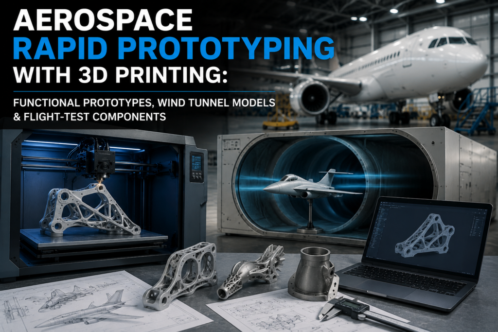
Aerospace programs run on iteration speed. A landing-gear bracket redesign, a new duct routing for an engine nacelle, or a revised wing-tip fairing all need to be in an engineer’s hands within days, not the six-to-ten weeks a machine shop typically quotes for a one-off metal part. That gap between design intent and physical validation is exactly what additive manufacturing was built to close. This guide walks through how aerospace teams in India and abroad use rapid prototyping to move from CAD to functional prototypes, wind tunnel models, and flight-test-ready components, and how to choose the right process, material, and validation path for each stage of a program.
What Is Aerospace Rapid Prototyping?
Aerospace rapid prototyping is the use of additive manufacturing and related digital fabrication methods to produce physical parts directly from CAD data, without the tooling, fixtures, or long lead times associated with conventional machining or casting. In an aerospace context, this covers a wide span of part types, from a lightweight foam-and-resin mock-up used to check cable routing inside a fuselage panel, to a nylon or aluminium bracket that gets bolted onto a test rig and subjected to real loads.
The defining feature is speed of iteration. A design change that would require a new CNC program, fixture, and machinist queue can instead be reprinted overnight, evaluated the next morning, and revised again the same week. For an industry where a single design freeze can cascade into months of downstream schedule risk, that compression in cycle time has a direct and measurable effect on program cost.
Why Aerospace Engineers Use Rapid Prototyping
Three pressures push aerospace engineering teams toward additive prototyping: schedule compression, the cost of late-stage design changes, and the need to validate complex geometry before committing to expensive tooling or certified production processes.
Faster Design Iteration
A typical aerospace bracket or housing can go through five to fifteen design revisions before it is locked. Printing each revision in FDM or SLS nylon, rather than machining it, routinely cuts iteration time from weeks to days, letting design teams converge on a final geometry earlier in the program.
Lower Cost of Early-Stage Mistakes
Catching an interference fit or a mounting-hole misalignment on a printed prototype costs a few thousand rupees and a day of turnaround. Catching the same issue after a metal part has been machined, heat-treated, and inspected can cost lakhs and push a milestone by weeks. Rapid prototyping shifts error discovery to the cheapest possible point in the process.
Design Freedom for Complex Geometry
Aerospace parts frequently need internal channels, lattice structures, or organic surfaces that are difficult or impossible to machine conventionally. Printing lets engineers explore these geometries early, well before a part goes anywhere near a certified production line.
Types of Aerospace Prototypes
Not every prototype serves the same purpose, and matching the prototype type to the design question being asked is what keeps a program efficient. Aerospace teams generally work across four categories.
Form and Fit Models
These are low-cost, dimensionally accurate parts used to check how a component sits within an assembly – clearances, mounting points, cable and hose routing. Surface finish and mechanical strength matter far less here than dimensional accuracy and turnaround speed, which is why FDM is the default choice for this stage.
Functional Prototypes
Functional prototypes are built to be handled, assembled, and in many cases load-tested. They need to survive actual mechanical stress, not just look correct, so material selection shifts toward engineering-grade nylons, glass-filled composites, or in some cases metal.
Wind Tunnel Models
Wind tunnel testing depends on precise aerodynamic surfaces and repeatable geometry. SLA and high-resolution SLS printing are widely used here because they hold tight tolerances and produce the smooth finish needed for accurate airflow data, particularly on scaled wing sections, fuselage segments, and control surface models.
Flight-Test Components
The most demanding category. Flight-test hardware often needs to be certified to specific material and process standards, which is where metal additive manufacturing (DMLS or SLM in titanium, aluminium, or Inconel alloys) comes in, alongside rigorous inspection and traceability documentation.
Best 3D Printing Technologies
The choice between FDM, SLA, SLS, and metal additive processes comes down to what the prototype needs to prove. For a detailed side-by-side breakdown of cost, accuracy, and material trade-offs across the three most common polymer processes, see our FDM vs SLA vs SLS Comparison, which covers the underlying technology differences in depth.
In an aerospace-specific context, the same technologies get applied with tighter tolerances and more conservative material choices. The table below summarises how each is typically used across an aerospace prototyping program, along with approximate Indian market pricing per part.
| Technology | Best For | Typical Accuracy | Approx. Cost (India) |
| FDM (Fused Deposition Modeling) | Form-fit models, jigs, ducting mock-ups | ±0.2-0.5 mm | ₹800 – ₹4,500 per part |
| SLA (Stereolithography) | Wind tunnel models, aerodynamic surfaces | ±0.025-0.1 mm | ₹2,500 – ₹15,000 per part |
| SLS (Selective Laser Sintering) | Functional prototypes, brackets, ducting | ±0.1-0.3 mm | ₹5,000 – ₹28,000 per part |
| Metal AM (DMLS/SLM) | Flight-test hardware, load-bearing parts | ±0.05-0.15 mm | ₹18,000 – ₹1,20,000+ per part |
Pricing varies significantly with part size, wall thickness, and post-processing requirements such as bead blasting, dyeing, or CNC finishing of critical surfaces – the figures above are representative starting ranges rather than fixed quotes.
Materials Used for Aerospace Prototypes
Material choice is often the single biggest factor separating a prototype that behaves like the final part from one that only looks like it. Aerospace teams typically work across a defined set of qualified polymers and metal alloys. We cover the full breakdown of properties, certifications, and selection criteria in Aerospace-Grade 3D Printing Materials, but the short version is below.
Engineering Polymers
PA12 and glass-filled or carbon-filled nylon variants (via SLS) are the workhorse materials for functional aerospace prototypes, offering a strong balance of stiffness, impact resistance, and light weight. PEEK and Ultem 9085 step in where flame, smoke, and toxicity (FST) requirements or higher temperature resistance apply, such as interior components and ducting near heat sources.
Photopolymer Resins
Standard and tough SLA resins are the default for wind tunnel models and aerodynamic surface studies, where dimensional accuracy and a smooth, paint-ready finish matter more than mechanical toughness.
Metal Alloys
Titanium (Ti-6Al-4V), aluminium alloys (AlSi10Mg), and nickel-based superalloys like Inconel 718 are used for flight-test components and structural brackets where strength-to-weight ratio and thermal performance are non-negotiable. These parts are typically printed via DMLS or SLM and go through post-print heat treatment, machining of critical surfaces, and full dimensional inspection before use.
Aerospace Design Validation and Testing
A printed prototype is only useful if the data it produces is trustworthy. Aerospace design validation using additively manufactured parts typically runs through three checkpoints.
Dimensional Inspection
3D scanning and CMM (coordinate measuring machine) inspection confirm that a printed part matches CAD within the tolerance band required for its test purpose – tighter for wind tunnel and flight-test hardware, looser for early form-fit checks.
Mechanical and Environmental Testing
Functional prototypes are subjected to load testing, vibration testing, and in some cases thermal cycling to confirm they behave predictably before a design is carried forward into a certified production process.
Wind Tunnel Correlation
For aerodynamic models, printed geometry is checked against simulation data (CFD) both before and after physical testing, helping engineering teams close the loop between predicted and measured aerodynamic performance early in a program.
Aerospace Applications
Rapid prototyping sits at the front end of a broader aerospace additive manufacturing workflow that, for many programs, extends into aerospace spare parts manufacturing for sustainment and MRO, and into aerospace tooling with additive manufacturing for jigs, fixtures, and layup tools used during production. The main prototyping applications include:
- Structural brackets and mounting hardware evaluated for fit before machining a final metal version
- Ducting and airflow components tested for internal geometry and pressure drop
- Scaled wind tunnel models for wing, fuselage, and control surface aerodynamic studies
- Interior cabin components and panel mock-ups for ergonomic and installation review
- UAV and drone airframes prototyped end-to-end before committing to composite lay-up tooling
- Engine and nacelle component mock-ups used for clearance and assembly sequence checks
Across all of these, the underlying logic is the same: use additive manufacturing to compress the number of physical iterations needed before a design is frozen and handed to certified production.
Future Trends
A few shifts are reshaping how aerospace teams approach prototyping heading into the second half of the decade. Multi-material and multi-laser SLS and metal systems are cutting build times significantly, shrinking the gap between a prototype and a near-production-representative part. Continuous fibre-reinforced FDM is pushing polymer prototypes closer to structural performance, useful for parts that need to survive more than a bench test. On the metal side, in-process monitoring and improved powder consistency are reducing the inspection burden on DMLS and SLM parts, making metal additive manufacturing viable earlier in a program rather than only at the flight-test stage. Digital thread integration – linking CAD, print data, and inspection records into a single traceable file – is also becoming standard practice as aerospace programs push additive parts further into certified workflows.
FAQs
How accurate are 3D printed aerospace prototypes?
Accuracy depends on the process. FDM parts typically hold ±0.2 to 0.5 mm, SLA reaches ±0.025 to 0.1 mm, and SLS and metal additive processes fall between ±0.05 and 0.3 mm depending on part size and post-processing. For wind tunnel and flight-test components, dimensional inspection via 3D scanning or CMM confirms the printed part meets the tolerance the application requires.
Can 3D printed parts be used in actual flight testing?
Yes, but only when produced through a qualified process and material combination, typically metal additive manufacturing such as DMLS or SLM in aerospace-grade titanium or aluminium alloys, followed by heat treatment, machining of critical surfaces, and full dimensional and material inspection. Polymer prototypes are generally used for ground testing, form-fit checks, and non-flight-critical evaluation rather than for flight hardware itself.
Which 3D printing technology is best for wind tunnel models?
SLA is the most common choice because it produces smooth, dimensionally accurate surfaces that are critical for reliable airflow data. High-resolution SLS is also used for models that need to survive repeated handling or higher tunnel speeds without deforming.
How much does an aerospace prototype cost in India?
Costs vary widely by process and part complexity. FDM form-fit parts typically start around ₹800 to ₹4,500, SLA wind tunnel and aerodynamic models range from about ₹2,500 to ₹15,000, SLS functional prototypes run roughly ₹5,000 to ₹28,000, and metal additive parts for flight-test use can range from ₹18,000 well into six figures depending on alloy, size, and post-processing.
How long does it take to get an aerospace prototype printed?
Simple FDM or SLA parts can typically be turned around in 24 to 72 hours. SLS functional prototypes usually take 3 to 5 days depending on batch scheduling, and metal additive parts requiring heat treatment and machining generally take 1 to 3 weeks from file to inspected part.
What materials are used for functional aerospace prototypes?
The most common are PA12 and reinforced nylon variants for general functional testing, PEEK and Ultem 9085 for high-temperature or flame-smoke-toxicity-sensitive applications, and titanium, aluminium, or Inconel alloys via metal additive manufacturing for load-bearing or flight-test hardware.
Conclusion
Rapid prototyping has become a standard part of the aerospace development toolkit because it directly attacks the two biggest cost drivers in any program: time and late-stage rework. Whether the goal is a quick form-fit check, an accurate wind tunnel model, or a flight-test-ready metal bracket, matching the right process and material to the right stage of validation is what makes additive manufacturing genuinely useful rather than just fast. 3D Protofarm’s 3D Printing Services support aerospace teams across this full range, from early concept models through functional and metal prototypes, with the process guidance to match.